Notices: Grzegorz Jagodziński |
|||||||||||||||||||||||||||||||||
One-Track Line in Train SimulatorsPart 1 |
|||||||||||||||||||||||||||||||||
|---|---|---|---|---|---|---|---|---|---|---|---|---|---|---|---|---|---|---|---|---|---|---|---|---|---|---|---|---|---|---|---|---|---|
Basics, definitions, etc. |
|||||||||||||||||||||||||||||||||
In real, trafic on single track lines is controlled manually. In the following article I try to answer the question if the control may be fully automatic. This is an important question for developers of many train simulators. The following analysis is partially based on real procedures used by Polish National Railways. Also definitions are similar to these which are used in Poland. All signals on schemes are also placed on the right, like in Poland. Let’s start from some definitions.
A semaphore is a device which informs whether the way is free or not. As it will be shown below, a semaphore can also bring information on the next signal, so the signal shown on a semaphore is a “main signal” combined with a “distant signal” in fact. Considering the form of the signals, two main types of semaphores are distinguished. They are colour-light semaphores and mechanical semaphores.
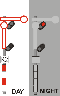
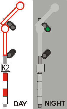
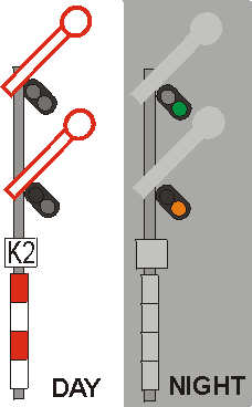
Considering assignment, some types of semaphores can be distinguished. On a one-track line, two main types are crucial. They are entry (“home”, “entrance”) semaphores and departure (“start”, “platform exit”) semaphores. In Poland, 17 signals may be shown on colour-light semaphores while only 3 signals on mechanical semaphores. Two of them are the most important: Free Way and Stop.
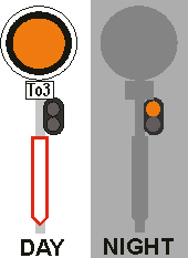
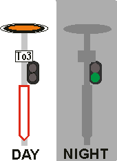
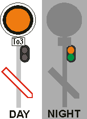
In Poland, manually controlled semaphores must have red and white strips on their posts (masts, pillars; see the pictures above). In fact, they are semi-automatic. A warning shield is another signalizing device, not being a semaphore. It shows so called “distant signal”. It means that there is impossible to stop the train before a shield. All a shield can do is to warn the train driver that the next semaphore shows the Stop signal. Like semaphores, warning shields may also be colour-light and mechanical. Note that mechanical warning shields does not resemble mechanical semaphores at all. Colour-light shields may look like colour-light semaphores – but as they are provided with a special sign (see here) and they have no red and white strips on the post there is no possibility of confusion. Besides, signals shown on warning shields and semaphores have actually the same meaning.
Note that a shield is not a semaphore. So, “the semaphore” means the next signalling device, not the shield itself. But in fact the same signal (one orange) may be shown on a semaphore which precedes another semaphore (see below, situation 2). Then the meaning of the signal is “the next semaphore gives Stop”. As it can be seen, the signal “the (next) semaphore gives the Stop signal” is orange, not yellow – it is a Polish peculiarity. It does not say “slow down”. But because the next signal (on the next semaphore) is red (“Stop”), the train driver must prepare to stop the train. A typical station on a one-track line has two tracks and platforms (in fact, there may also exist additional tracks for goods trains): 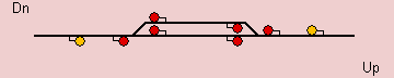 Dn (for Down) and Up are directions on the line, not used in Poland practically, however very comfortable and thus used here. The two tracks are the main track (the lower one on the scheme) and the loop track (the upper one). Both tracks are bidirectional, i.e. both up and down trains can use either track. Notice those two orange signals on warning shields – that can never show red. A block (section) is a part of a line between two semaphores, one of them is entry one and the other departure one. A very important notice is that sectioning of a bidirectional line is different for up and down trains. Any simulator should pay attention to this. We may also distinguish smaller sections, or segments, taking into consideration both directions. However, we must not forget that such segments are not real blocks of the line.  On the scheme above, blocks for an up train are: 1, 2+3, 4+5, 6+7, 8+9. For a down train, blocks are: 9, 8+7, 6+5, 4+3, 2+1. So, there are 5 blocks for either directions. Note that warning shields do not limit blocks (or segments). Segments (not: blocks!) 1, 5, and 9 are situated entirely outside stations, between two entry semaphores (each for either direction). Such a segment is nothing more but a trail (see above for the definition). Segments 2, 4, 6, 8 are places where junctions are situated. We will call them station headers, or shortly headers. Segments 3 and 7 are situated between departure semaphores for both directions. These are platform tracks, or platforms for shortness (even if real platforms may be a little shorter than platform tracks). The shortest platform track must not be shorter than the longest train that can be used on the line. Trains that are longer than the shortest platform track cause problems of a special kind which will not be analysed here. Note that basically, there are two kinds of blocks (valid only for one of the two directions):
The actual boundaries of a block depends on the state of the junctions and the position of the train. Namely, when a train enters the station, both the header and the platform must be counted as occupied. But when the very end of the train passes the entry junction (in practice: when the entire train is on the platform track, i.e. when it has passed the departure semaphore for the other direction), the station-master can switch the junction, and then the train does not occupy the header any longer. A train which has left the station completely (i.e. its very end has passed the entry semaphore for the opposite direction) does not occupy the header any more. It means that e.g. it is free for shunting – but not for another train to departure. Note that semaphores do not control strictly either blocks or segments. In other words, it does not exist a strict and unanimous relation between the state of the block or segment, and the signal shown on the semaphore. We will show it below. |
|||||||||||||||||||||||||||||||||
The main signalizing rule on a one-track line |
|||||||||||||||||||||||||||||||||
The base signal given on manually controlled semaphores is always Stop (red). In practice, it causes not less than 3 states of a segment (in fact, there are more of them, see below):
The neutral state and the free state differ in the signal on the delimiting semaphore: it is Stop or Free Way, respectively. |
|||||||||||||||||||||||||||||||||
A voyage on a one-track line |
|||||||||||||||||||||||||||||||||
In the real world, the station-master has some information of trains, and using this information he can set all needed junctions and signals. A simulation is nothing more than an emulation of the real world, and should be as similar as possible in order to work properly. It is not true that a good timetable or manual control is needed to avoid locking the layout up. Real trains not always go in strict accordance to the timetable. Late trains and special trains are examples of potential problems. Anyway, station-masters must solve these problems somehow, using definite procedures, and it is also possible for a simulation (all procedures may be replaced by a computer program). All we must determine is the minimal information we must have in order to make decisions properly. A virtual voyage along a one-track line may be a good idea for stating what is needed and what should be the proper rules. This is the first part of our line:  We start from the A station (which may be a terminus station for simplicity), and go in an up train to B and next to C. Let the symbols for the departure semaphores of the A station be AB1 (the upper platform), AB2 (the middle platform, or the main track), and AB3 (the lower platform). Let the entry semaphore to the B station (from A) be AB. Let ShAB be the shield before the semaphore. For the opposite direction, the entry semaphore to A will be termed BA. |
|||||||||||||||||||||||||||||||||
Ready to start |
|||||||||||||||||||||||||||||||||
1 We are at last in out train which is waiting for departure by the second (middle, main) platform of the A station. Our train is always drawn green. We are stopped at the red signal (Stop) however. 1. It is so because the white train has already left the B station, and is on its way to A. Note that the trail (between the two stations) is reserved (or: allocated) for the white train, even if it is not on the trail yet (the first part of the train is occupying the header while the rest is still on the platform track). We must wait until the train reaches a platform in A, and until its releases the header of A. 2. Even because the current block for the white train (for its front part, speaking more accurately) ends up at the entry semaphore to A (i.e. BA) which is still giving Stop (for some unknown reason), the station-master (or: the simulator) cannot reserve the header for our train. It is so because the next semaphore for our train is the entry semaphore to B (AB), beyond the trail. So, in order to reserve the header for our train, the station-master would have to reserve the trail as well – both segments are in the same block for our train (even if not for the white train). It is impossible because the other train has already the trail reserved for itself (even if it has not reached it yet). In other words, the header of A is closed for our train because it is a part of a block whose another part (the trail) has already been reserved – it is a part of another segment whose another part has already beeen occupied by a different train. Any violation of this quite complicated rule could lead to locking up the layout, or even to a collision. |
|||||||||||||||||||||||||||||||||
2 On another scheme the departure semaphore for our train shows Free Way: 3. Our departure semaphore AB2 is showing Free Way because the next block for our train is free, i.e. both the header and the trail up to the next semaphore (AB) are free. The simulator must check it before it gives Free Way. This condition is necessary but not enough. 4. As AB2 is showing Free Way, the departure junctions must be set for our route. It is obvious that both AB1 and AB3, the two other departure semaphores, must show Stop then, protecting other possible trains from entering the header, and it is not the “neutral” stop. So, the rule is that only one of departure semaphores may show Free Way in this situation. Or, a semaphore must check the state of all junctions up to the next semaphore. 5. The train which is standing at B (the white arrow) is being given the Stop signal. It is so because the trail (BA – AB) has already been reserved for our train, and in order to give Free Way, the trail should be reserved for the white train. The left junction at B is set for the main track, not for the loop track (the one with the white train waiting). The setting, once made, should not be changed in normal situations. 6. For a plain passenger train on a one-track line which stops in each station, the reservation should not be set up beyond the platform of next station, for a number of reasons. That is why the departure semaphore BC2 is giving Stop. However, as we will see, sometimes the station-master must know (or: the simulator must check) the further way as well. 7. Note that the entry semaphore in B (i.e. AB) is orange, not green. This signal (in fact, orange in Poland) means that the next semaphore is showing Stop (“the next” means the departure semaphore BC2). So, each semaphore must be able to read the signal shown on the next device. It is not a wise idea to do this with the help of scripts manually added to every semaphore on the simulation because of their number. It is the simulator (the program), not the layout-maker, who should find which semaphore is the next. Note that it will be modyfied during the simulation, as junctions will switch.
8. The green signal on the shield ShAB before the orange signal on the next semaphore is correct: it means that the train need not reduce the velocity at the next semaphore (i.e. the entry semaphore AB). In fact, it is showing no velocity reduction – the orange signal does not mean any reduction now (but stop by the next semaphore). 9. Before we have got green (on the departure semaphore AB2), the station-master of B (or: the simulator) checked if any of the platforms is free and ready for accepting our train. He also checked if any shunting is needed on the left header. Because there is a train standing on the loop track and ready for the departure to A, and the main track is free, no shunting is possible at all. This is not the most important rule for the simulator and may be omitted. 10. Our departure semaphore AB2 is showing Free Way because we start from the main track. So, the simulator must know whether the track is main or not. It would not be too comfortable for the user to set this flag manually for each semaphore! In fact, it should be easy just to count angles by any junction to determine if a track is main or not. |
|||||||||||||||||||||||||||||||||
3 The situation on the next scheme should be avoided – but it can happen sometimes when many trains are on a one-track line. It is not dangerous but should be treated properly. Another train (white) is occupying the main track in B, so our train (green) will arrive on the loop track. 11. The left junction in B is set to the loop track then. It means that our train must slow down before it reaches the junction; in typical instances the allowed velocity is 40 km/h. This is signalized by the AB semaphore which shows two orange instead of one. In Polish signalization system, such two-lamp signals should be read in a simple way: the lower lamp shows what is allowed now, by the semaphore while the upper lamp warns against what the next semaphore shows. The meaning of both orange lamps is different however. The “current” orange lamp (the lower one) informs that the maximal velocity is reduced to 40 km/h starting from now. The “next” orange lamp (the upper one) informs that the next semaphore (BC1) shows Stop (just like if it was a single orange signal). In other words, the signal shown on a given semaphore should depend not only on the signal on the next semaphore (see 3 above) but also on the state of the junction(s) on the way. It should be fully automatic in a simulation, without the need of writing scripts for each semaphore.
Note that the mechanical semaphores cannot give so specific signals as colour-light semaphores – they do not inform what signal is shown on the next semaphore. In addition, the velocity limit given on a mechanical semaphore is restricted not to the next semaphore but to the end of so called “junction district”. In typical situations, a train slowed down to 40 km/h by a mechanical semaphore may accellerate to normal velocity when passed the last junction (in the station header). 12. The double orange signal shown on the semaphore AB is announced by the proper signal on the shield ShAB. The shield is giving flashing orange. Its meaning is “the next semaphore is showing the velocity limitation” (to 40 or 60 km/h, to be accurate).
|
|||||||||||||||||||||||||||||||||
4 The situation on this scheme is similar to the 2nd one – except that our train (green) is starting from a branch track. 13. The AB3 semaphore is showing the adequate signal: now Free Way with Speed Limit to 40 km/h (the lower orange lamp) and next Free Way (at full speed, the upper green lamp). Such a signal lit on a departure semaphore is valid to the end of the station (more accurately: until the last wheels of the last wagon pass through the last junction of the header of the station), not to the next semaphore. A good simulator must be able to accelerate the train when it leaves the header then, even if there is no another semaphore there. No scripts should be needed for this. Note also that a departure semaphore located at a branch platform track can never give just Free Way, it may only give either Stop or Free Way with Speed Limit.
If the departure semaphore is mechanical, the signal does not difer from the one previously discussed. |
|||||||||||||||||||||||||||||||||
5 Another strange situation which should not happened. It is similar to 3 except that the departure semaphore BC1 shows free way. As our train must go through the loop track, not through the main track (with the white train already occupying it), the signal cannot be just green (loop tracks cannot get Free Way at all). Instead, the signal says: go not faster than 40 km/h (the lower orange lamp), and at the full speed when you pass the (last) junction (the upper green lamp), see the same situation in 4, station A. 14. But the entrance to the station B need also changing the track which have to be done with limited speed. That is why the entry semaphore AB also shows the limit of 40 km/h. As the next semaphore (BC1) shows the same limit, the signal must be: speed limit here and there, or more precisely: go at maximal speed of 40 km/h by this and the next signalling devices.
As mechanical semaphores cannot give information what the next semaphore shows, the signal on such a semaphore would be just “speed limit”. Now we know the basic part of the code which is used on signalling devices in Poland. If a single lamp is lit:
If the signal contains of two colours, the meaning of the upper and the lower lamp differs. The lower lamp is orange and means the speed limit (to 40 km/h) now, by this signalling device. The upper lamp shows what should to be expected by the next signalling device. Note that when there is a speed limit, the device must always show what signal is shown on the next device, and the upper lamp is used for this.
Telling the truth, the Polish signalling system is much more complex. It has also signals for speed limits to 60 and to 100 km/h. But in this article only 7 of the total number of 17 main signals are presented, we will not discuss old system, shunting and repeating signals either (see here if interested). |
|||||||||||||||||||||||||||||||||
6 The situation on this scheme is very similar to the previous one. The only difference is that the entrance to the B station is still closed for unknown reason. Maybe just because some shunting in B takes place – the trail between A and B is long enough that they would have been finished by the arrival of the green train. 15. The signal on AB3 is the same as previously. And like previously, it means that the green train is allowed to depart but must not exceed the speed limit of 40 km/h when passing the header of the station. But when it leaves the junction completely, it may accellerate to the maximum allowed speed (the simulator must know it). Even if the next semaphore is AB and it is showing Stop, we need not warn about this fact on AB3. It is so because of the shield ShAB which is on the way. It is giving orange which means Full Speed But Stop on the Next Semaphore. Which is more, a shield can never show a speed limitation from itself, it only warns against the signal shown on the next semaphore. Thus from the clearly practical point of view, the simulator may just check the state of next signalling device (independently on whether it is a semaphore or a shield). However, the orange and green signal (on AB3) does not mean: go at 40 km/h up to the next signalling device (which is the shield ShAB). It rather means: go at 40 km/h until you leave the last junction of the station. A simulator must “know” then when the train can accellerate not only from signalling devices but also from junctions. |
|||||||||||||||||||||||||||||||||
Continuation |
|||||||||||||||||||||||||||||||||
Polish Railway Signals |
|||||||||||||||||||||||||||||||||